Slide 8 of 16
Notes:
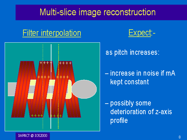
On a multi-slice scanner, a filter interpolation method is generally used. The width of the chosen filter, shown here in yellow, defines the resultant imaged slice width, and all the data points within that width at a given projection angle are used in the interpolation – there are three points within the filter in this illustration.
For a given imaged slice width, the filter width remains the same regardless of pitch. But, as pitch increases, the number of data points within the filter decreases. We expect this to result in an increase in noise with increasing pitch at fixed mA, and also possibly to cause some degradation of the z-axis profile shape.
Let us look at to what extent these expectations are borne out in our measurements.